

How to Set Z-Axis Zero on a CNC Router





Setting the Z-axis zero point correctly is an essential step in CNC router operation. It helps ensure accurate cutting depth, consistent machining results, and better workpiece quality. Whether you are processing wood, acrylic, aluminum composite panels (ACP), or other sheet materials, proper Z-axis zero setting is important for reliable CNC machining.
This guide explains how to set Z-axis zero on a CNC router, including tool positioning, zero calibration, and common mistakes to avoid.
1. Prepare the CNC Router
Before setting the Z-axis zero point, check that the workpiece is securely fixed to the worktable. Make sure the cutting tool is properly installed and the spindle is in a safe position.
Confirm that the correct tool and machining program are selected. For ATC CNC routers, verify that the tool number and tool length information match the selected program.
2. Move the Tool to the Workpiece Surface
Use the CNC controller to move the spindle above the intended machining area. Slowly lower the tool toward the workpiece surface using the Z-axis jog controls.
Keep the spindle stopped during manual positioning. Leave enough clearance to prevent accidental contact between the tool and the material.
3. Set the Z-Axis Zero Point
The exact procedure depends on the CNC controller and machine configuration. Common methods include:
Manual setting: Carefully position the tool at the selected reference surface and set the Z-axis work coordinate to zero.
Tool setter: Use a compatible tool-length sensor to measure the distance between the tool tip and the reference point.
Automatic tool measurement: On supported ATC CNC routers, use the configured tool measurement routine to record tool length and compensate for differences between tools.
Follow the machine manufacturer's instructions for the controller's zero-setting procedure. Do not assume that machine coordinates and work coordinates use the same zero point.
4. Check the Zero Setting
After setting Z-axis zero, verify the displayed work coordinate and confirm that the tool is positioned correctly relative to the workpiece.
For a new setup, perform a safe test movement or a controlled test cut in a suitable area. Check the actual cutting depth before starting full production.
For ATC machines, confirm that tool-length compensation is configured correctly for each tool used in the program.
5. Common Z-Axis Zero Setting Problems
Incorrect cutting depth: Check the workpiece surface reference, tool length, and active work coordinate system.
Tool cuts too deeply: Stop the machine and inspect the zero point, tool offset, and program settings before restarting.
Different depths between tools: Verify tool-length measurement and compensation, especially after an automatic tool change.
Inconsistent results between workpieces: Check whether the material thickness, workholding position, and reference surface have changed.
6. Tips for Accurate CNC Router Operation
Secure the workpiece before setting zero.
Use the correct tool-length measurement method for your machine.
Recheck the Z-axis zero point when changing tools or workpiece setups.
Keep the tool setter and reference surface clean.
Follow the controller manual and machine safety procedures.
Conclusion
Correct Z-axis zero setting is essential for accurate CNC router cutting depth and consistent machining quality. By following the correct procedure and checking tool-length compensation, operators can reduce setup errors and improve production reliability.
ANBEN CNC routers support a range of panel-processing applications. Always follow the specific operating instructions for your machine model and controller.
 How to Set Z-Axis Zero on a CNC Router
- When Should You Upgrade to an ATC CNC Router?
- Daily CNC Router Maintenance Checklist for Operators
- Horizontal or Vertical CNC Router for Large Panel Production?
 What Is CNC Nesting and How Does It Reduce Material Waste?
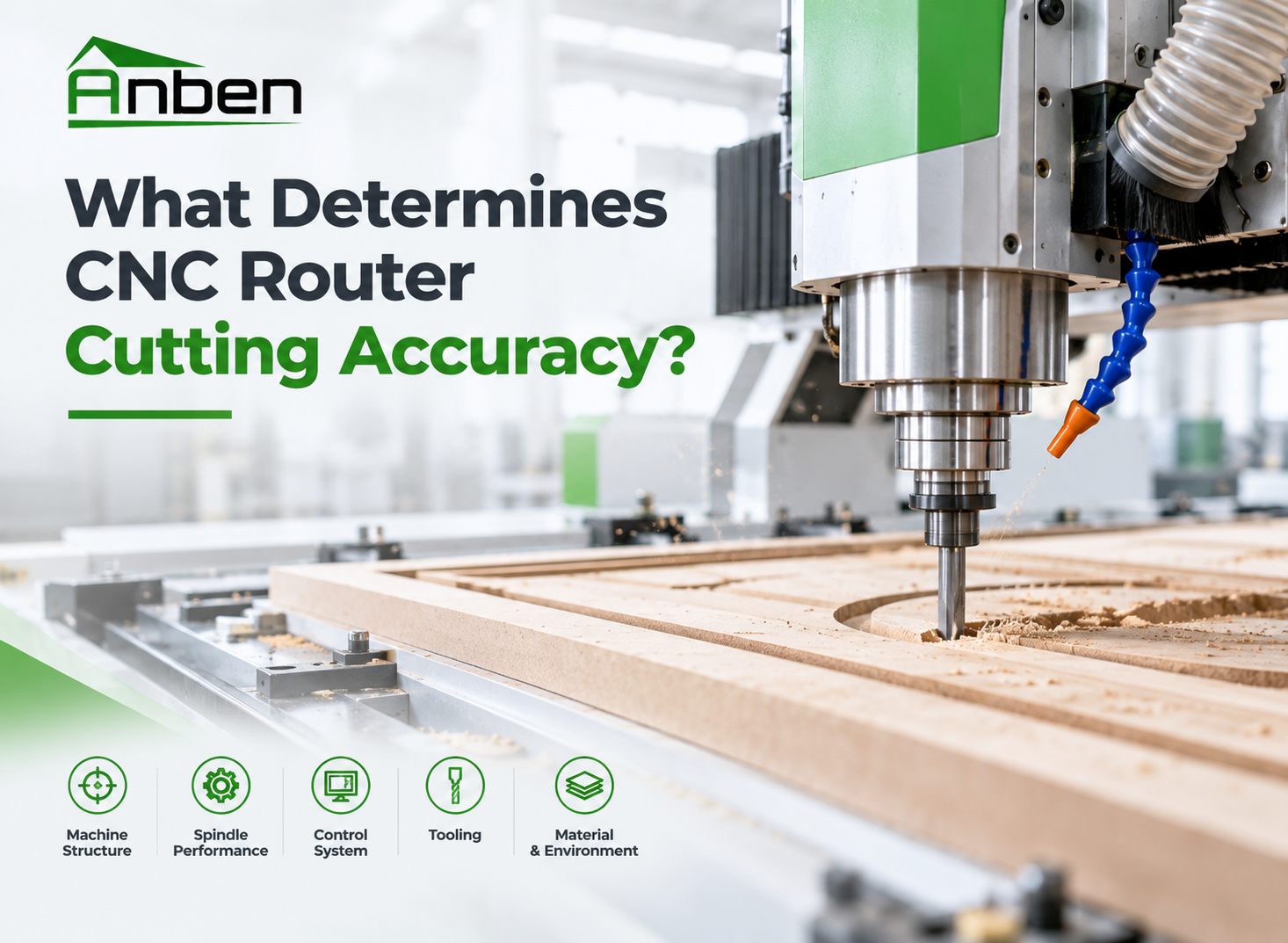
- What Determines CNC Router Cutting Accuracy?
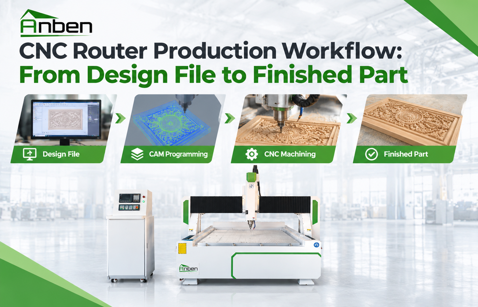
 CNC Router Production Workflow: From Design File to Finished Part
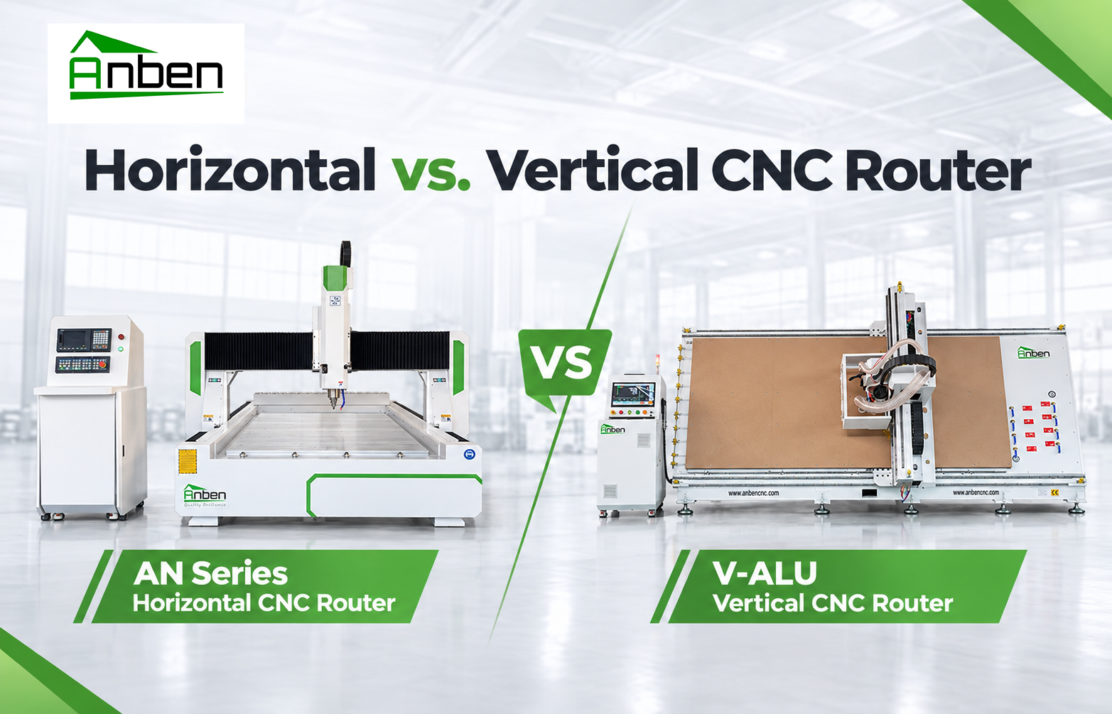
- Horizontal vs. Vertical CNC Router: Which One Is Right for You?


Related Products
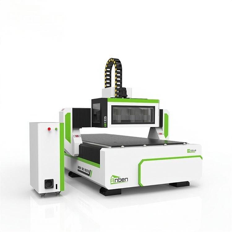
 AN1325-3S Cnc Router 3 SpindlesAnben multi spindles CNC router has 3 or 4 spindles, each spindle use different tools and work one by one. It also called economical ATC cnc.
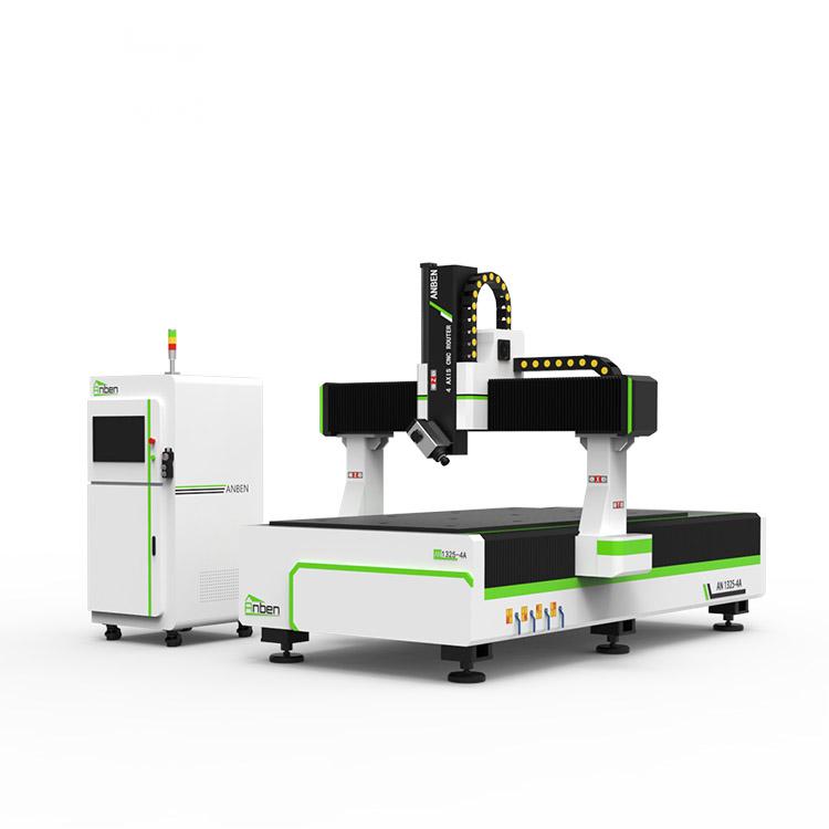
 AN1325-4 axisAnben 4 Axis CNC Router Machine with 4 axis ATC spindle is good at heavy-duty and complex 3d wood cutting and carving of wood panel, MDF, plywood, etc. All the working areas and specifications can be customized according to your requests.
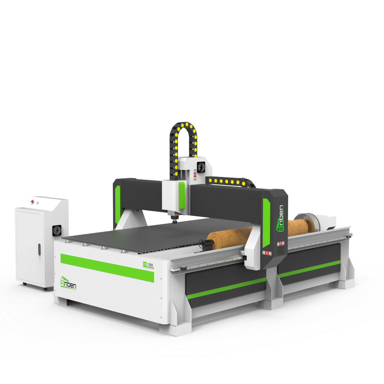
 AN Cnc Router With Rotary AxisAnben cnc router with Rotary Axis for businesses that need both flat and rotary carving in one machine. From staircase spindles to decorative columns, this type of router handles round parts with ease. It’s a smart pick if you’re working with furniture, signs, or wood crafts that involve turning or 3D shapes.
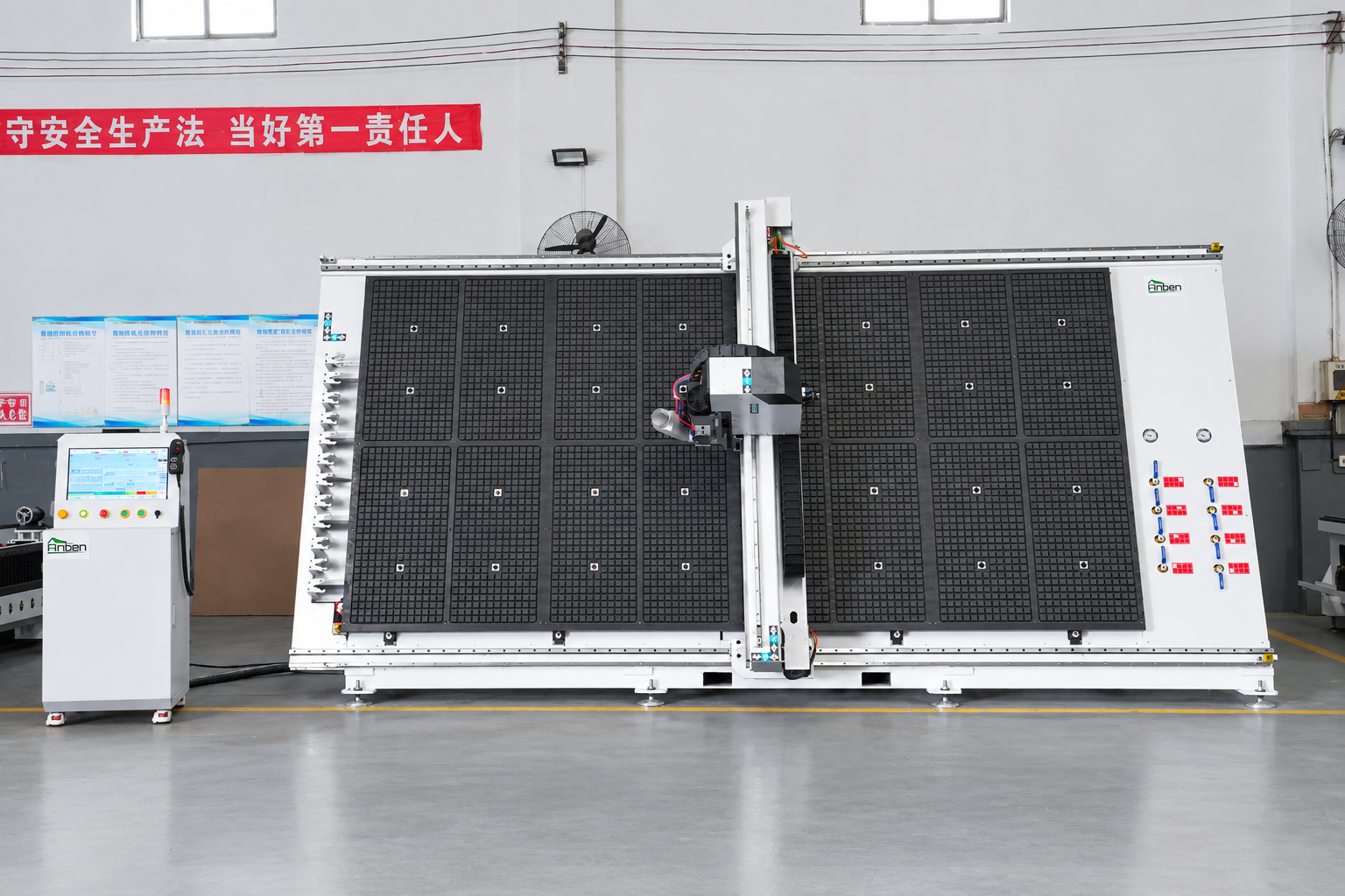
 V-2142 Vertical cnc routerThe vertical cnc significantly reduces the machine’s floor space. It is equipped with 8 sets of ATC tool magazines and other auxiliary devices such as vacuum pump, saw blade,aggregate head, positioning systems, etc. The Vertical cnc can cutting,grooving,engraving,drilling for various types of aluminum composite boards, acrylic boards, fiber boards and other boards. It is suitable for construction facades,cladding ,advertising signs,furniture manufacturing and other industries.
Get in touch

Anben Industrial – Founded in 2017, with a pure engineering spirit, providing trustworthy CNC solutions, born for long-term stable performance.
Contact